Modifying my Casio PT-10 toy keyboard to become a synthesizer
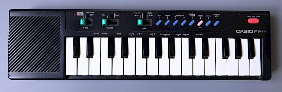
I recently rediscovered my Casio PT-10 from my childhood, which still works flawlessly after being put away for probably over 30 years. Only now, I learned that my toy keyboard is related to the Casio VL-1 of some pop music notoriety. In a weird design decision, Casio included a calculator in the VL-1. In an even weirder decision, the calculation result stored in memory can be used to create a custom voice. It gives you the choice between several base sounds that can be customized in terms of envelope, vibrato and tremolo. Hence, the VL-1 is sometimes considered the first cheap programmable digital synthesizer.
However, Casio did not include the programmable voice in the PT-10, giving it only four fixed voices: piano, fantasy, violin and flute, three of which very vaguely sound like the instruments they are named after. Since the PT-10 uses the same CPU as the VL-1, I decided to modify my PT-10 in order to add the missing programmability. Armed with the schematic from the PT-10 service manual and a description the keyboard matrix of the VL-1, I disassembled my PT-10. Notice how Casio got away with a single-layer PCB: by routing carbon traces – the same carbon as used for the contacts – over the solder resist, so they can cross the regular copper traces.

Two modifications need to be done to enable the programmable synthesizer. The voice selection switch needs to gain an additional position to switch to the custom voice – called ADSR in the Casio VL-1 manual. The function switch also needs to have another position (besides record and play) to access the calculator mode. In both cases, I decided to cut the common traces going to the respective switches and to add SPDT options. In that way, I can either reconnect the original switch – which makes the keyboard operate as before – or access the additional functions: calculator and ADSR voice. I tried using test points and “vias” (from copper to carbon trace) as much as possible. I cut the traces with a scalpel. I scraped off the carbon or solder resist to expose the copper, put a bit of non-corrosive flux on the copper and tinned the exposed trace with the soldering iron. Then I soldered six wires to respective points.


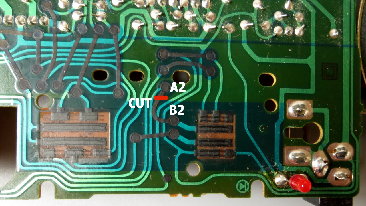
Here is a photo of the end result. I made sure to route the wires so they stay clear of switches and buttons. For the time being, I have soldered a 6-pin header to the wires and use jumpers to switch between the settings. I haven’t decided yet if I want to permanently modify the plastic case by drilling holes for switches. As it stands now, if I opt to undo the modifications, I just need to desolder the wires and fix the two cut traces.

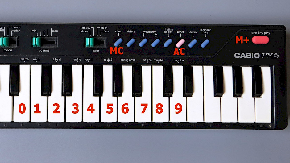
To program a custom voice, I switch the keyboard into record or play mode and then move the jumper over to A2-C2 to enable calculator mode. The power LED switches off. This confused my initially. However, the power LED is tied to the audio section, which is off in calculator mode. Obviously, without display, I have to type blind. I press clear (MC) to make sure the calculator memory is zeroed. Then I use the keys to type in an 8-digit code. If I mistype, I can use reset (AC) to start again. Finally, I store the value in memory with one key play (M+). Then I move the jumper back to its original position A2-B2, to switch back to record or play mode. The other jumper needs to be set to A1-C1 enable the ADSR voice. All other functions of the keyboard – such as the sequencer of the rhythm selection – keep working like before.

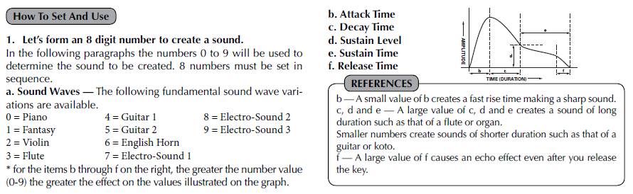
The meaning of the eight digits is explained in the Casio VL-1 manual. Here are some examples, recorded from the keyboard’s speaker with a microphone. Perhaps I should add a line-out jack…
0000 0000: a very short blip sound
3045 3233: a warm synth sound, based on the Flute voice
6107 9130: the English Horn example from the VL-1 manual
7009 9077: the Electro-Sound 1 voice with a lot of tremolo and vibrato