Preserving a floppy disk with a logic analyzer and a serial cable
Introduction
Being involved with retro computers, I have a few floppy disks (of the 3.5-inch variety) that I would like to preserve as faithfully as possible. Of course, I know there are dedicated devices for doing that, such as the Kryoflux or the SuperCard Pro. But it occurred to me that I already own the required hardware to capture the low-level data from a floppy disk: my Saleae Logic 8 logic analyzer.
Side note: While I can only highly recommend the Saleae analyzers for their features and easy-to-use software, the things described here can also be done with other logic analyzers – including those available for less than 10 € from your favorite Chinese online store – and using, for example, the free Sigrok software.
A primer on the floppy drive interface
Contrary to more modern mass storage devices such as ATA hard drives or USB sticks, the interface to a floppy drive is much more low-level. E.g., you can ask a modern hard drive to read sector 1337 and it will return you the bytes stored in that sector. In contrast, as soon as it is selected for reading and the disk is rotating, a floppy drive will simply give you a pulse each time the magnetic flux changes, i.e. whenever the magnetic field changes orientation. It is important to know that the magnetic field orientation does not directly represent the individual bits that are stored on the disk. Instead, an encoding scheme is always used. The details of the encoding differ between systems – which is why you cannot read an Amiga disk in an Atari ST, for example. Regardless of the implementation, the encoding always needs to take care of several things: 1. Encode the data bits, obviously. 2. Clock recovery. This is essential because different drives may rotate at slightly different speeds and the floppy disk controller thus needs to determine the actual data rate. 3. Marking the start of a sector. This is often achieved by flux patterns that do not occur in regular data.
The following examples will consider MFM (modified frequency modulation) encoding as used in IBM PCs and Atari STs. It is important to note, however, that the floppy disk imaging is performed at raw flux level and as such will work with every encoding.
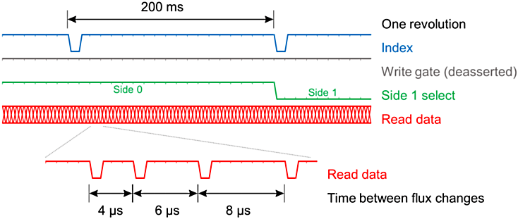
This image shows the signals involved in reading data from a floppy disk. The write select signal, write gate, is forced high, which means deasserted, since floppy disks use active low logic signals. Then the disk drive will return flux transitions as pulses as described above on the read data line. Only the falling edge is relevant.
Furthermore, so that you know the duration of one revolution of the disk, the index signal provides one pulse for every revolution. During that time – nominally 200 ms for a 300-rpm, 3.5-inch drive – an entire track on the disk is read. The side 1 select signal tells the drive which side of the disk to read.
If you zoom in on the read data signal, you will see that – for MFM encoding and DD (double density) disks – the flux transitions are 4 µs, 6 µs or 8 µs apart.
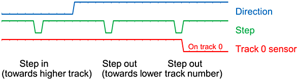
How to tell the drive which track to read? There is no command instructing the drive to seek to, e.g., track 42 by itself. You have to provide step pulses – again active low – for each step the drive head is supposed to make inwards (towards higher track numbers) or outwards (towards lower track numbers), depending on the direction signal. The track 0 signal indicates when the head is at the outermost track.
Connecting the logic analyzer and capturing a first track
With that knowledge, one can now connect the logic analyzer to the drive. The pinout of the floppy drive connector is shown below. All odd numbered pins are connected to ground.

Note: A drive taken from an IBM-compatible PC is configured as drive select B and, thus, needs the drive select B and motor enable B lines pulled low to be selected. Write gate of course needs to be pulled high. My drive is a modern one that only requires a +5 V power supply. Older drives might want the +12 V supply as well.
The output signals, such as read data and index, are open-collector, meaning that a pull-up resistor to 5 V is needed. To minimize cross talk between the flying leads, I used logic analyzer channels 1 and 3 as well as proper grounding. With a DD floppy disk inserted and the motor now spinning, one can capture a trace with the logic analyzer – preferably triggered on the falling edge of the index signal.
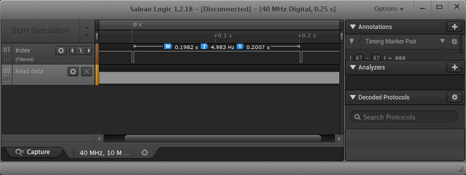
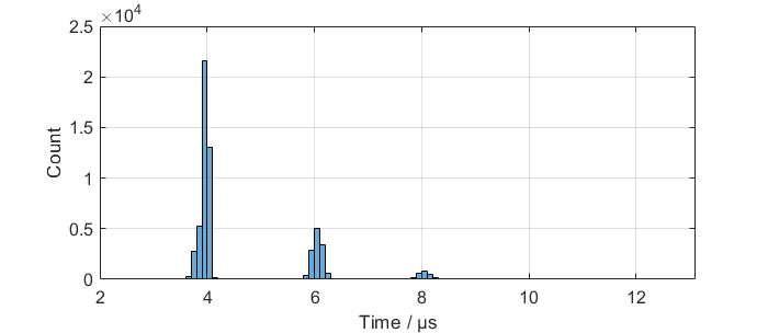
This looks as expected. A histogram of the times between flux changes confirms that indeed 4 µs, 6 µs, and 8 µs prevail.
Controlling the floppy drive
In order to move the drive head, I resorted to another bit of hardware that was available: a USB serial cable. Mine is from FTDI, but every cable should work that not only exposes transmit and receive signals but also the control lines. I made the following connections:
RTS → direction
DTR → side 1 select
TX → step
CTS ← track 0
GND = GND
RTS and DTR are outputs that can be controlled from the serial cable. CTS is an input. Using TX (the transmit line) as step signal means that sending a 0xff byte will cause a single step pulse to the drive because of the start bit of the serial transmission. I verified this to work with a terminal program that allows me to arbitrarily set the control lines.
Automating
Capturing all 80 or more tracks of a floppy disk means that the process needs to be automated. Python comes in handy. Of course, a serial port can easily be controlled from a Python script (via the pyserial module). Fortunately, the Saleae software can be remote-controlled and there is a Python module for that, as well. A minor issue I found is that the remote-control API does not expose all settings. Hence, I initialize the Saleae software from a previously saved settings file.
With my finished script, I can step through all the tracks on the floppy disk, capturing both sides, track by track, with the logic analyzer. Data is exported from the Saleae software and imported into Python for further processing. This mainly consists of trimming the data to one revolution of the disk by means of the index signal and of calculating the times between flux changes, i.e., the times between falling edges of the read data signal.
Exporting the data
Obviously, for preservation the captured data needs to be stored – preferably in an already established format. I decided to go with the Supercard Pro (.scp) file format, because it is well documented and understood by third-party applications such as emulators. An scp file stores times between flux transitions, exactly the type of data that I capture with my setup. The Python script was quickly extended to produce the correct format including headers.
Preserving the first disk
With hardware and software now in place, one can now test everything. For the first test, I chose an unimportant disk, just in case some malfunction would damage it. The script ran, the floppy drive clicking every time the head moved one track further inwards. And in the end, the scp file was generated! Its file size is roughly 14 MB. Considering that the disk only has a usable capacity of 720 kB, this shows how much more low-level information is preserved by imaging disks at magnetic flux level.
I used the HxCFloppyEmulator software to decode and interpret the data. It correctly decoded the individual sectors captured in the scp file, telling me that all 1440 sectors were decoded without error – proving that my setup works without any issues!
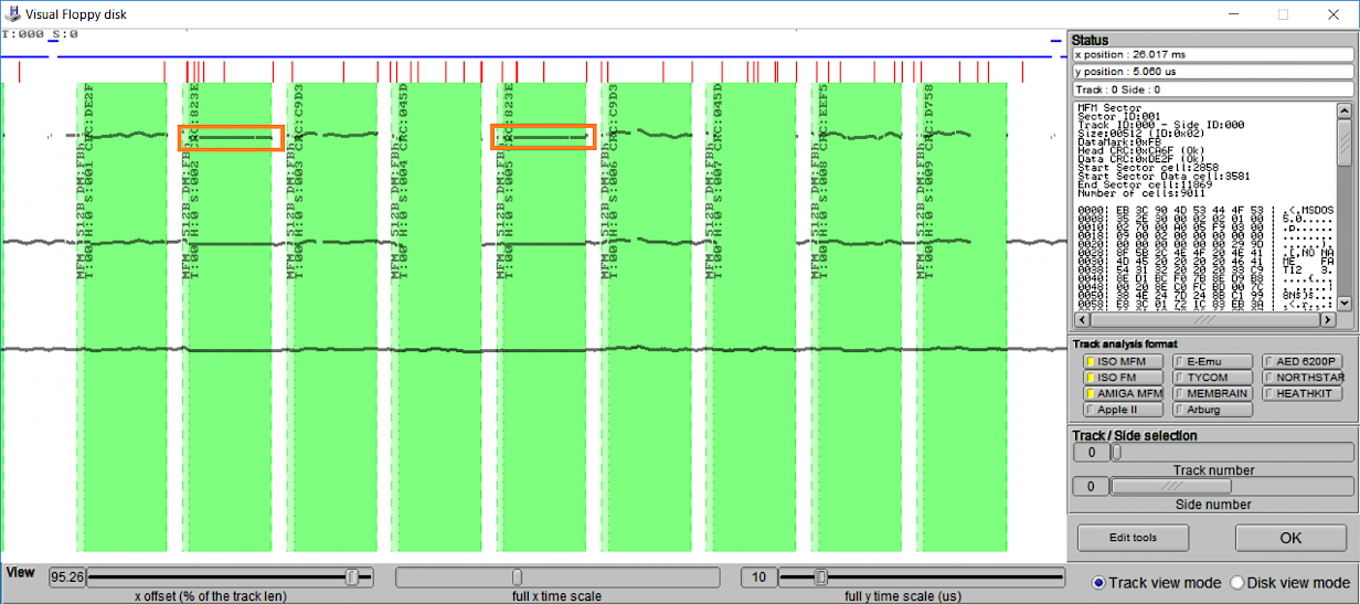
Also, one can make interesting discoveries. Consider this display of track 0, side 0 of my disk. The bit timings – drawn as thick gray lines – show the drive this disk was originally written with had some jitter, evidenced by the wavy lines. But the two sectors containing part of the FAT (file allocation table) were overwritten by a different drive with nearly perfect timing – marked by orange boxes. Thus, you can even use this data to “finger-print” a floppy drive.
Final remarks
If you want to this try yourself, you can find my Python script in https://github.com/czietz/floppy-and-logic-analyzer. You probably will have to adapt it to your hardware configuration.
There are some things that could be improved:
- The process is quite slow, requiring ca. 10 seconds per track, ca. 800 seconds for a full disk. Most of the time is spent in the Saleae Python API for capturing and exporting data. Perhaps, profiling can highlight potential bottlenecks.
- To reliably preserve defective (or copy-protected) disks, it is sometimes required to save multiple revolutions per track. The scp file format allows for it; my Python script could be extended accordingly.
- Since in my setup the drive motor is always on, I have to switch off the power supply before changing disks. By using one of the general-purpose output pins of my serial cable, the motor enable signal could be controlled. However, these output pins cannot be set via pyserial.